Обозначения, что есть что на Фукусиме
От человека с ником Dobryak:
Дэвид Локбаум, веселые и не очень истории которого из американских реакторных будней я приводил не раз, выложил два интересных репортажа пофукусимским снимкам высокого разреше. Переводить, увы, времени у меня нет. Если кто возьмется, низкий поклон:
Я тоже не буду, тут все просто, если что, есть гугл-переводчик
upd Внизу появился перевод (сорри, у меня времени нет, поэтому я его просто копирую с той же Авантюры.
Репортаж 1:
A set of very high-resolution photographs of the Fukushima Dai-Ichi nuclear plant have been posted on the web by cryptome.org. I’ve annotated some of those pictures below to help people know what they are seeing in those photos.
Photo 1: (original photo: Air Photo Service Co. Ltd., Japan)
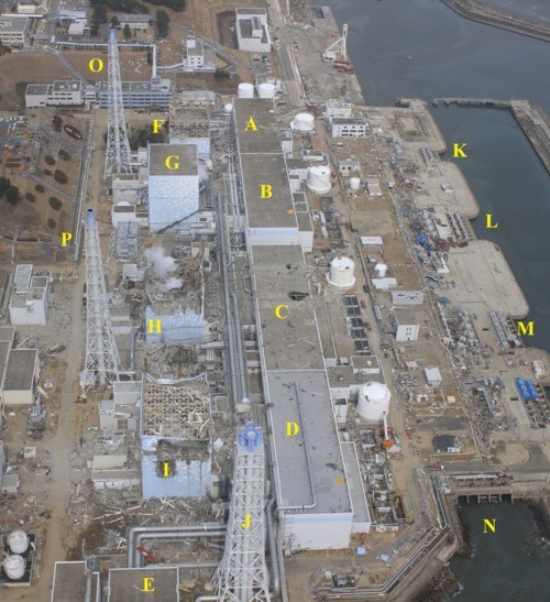
1A - Unit 1 turbine building containing the main turbine, main generator, condenser, condensate pumps, and condensate booster pumps
1B - Unit 2 turbine building containing the main turbine, main generator, condenser, condensate pumps, and condensate booster pumps
1C - Unit 3 turbine building containing the main turbine, main generator, condenser, condensate pumps, and condensate booster pumps
1D - Unit 4 turbine building containing the main turbine, main generator, condenser, condensate pumps, and condensate booster pumps
1E - Offgas building shared by all four units containing equipment to process air pulled from the condensers and reduce radioactivity discharged from the offgas stack during normal reactor operation
1F - Unit 1 reactor building with extensive damage caused by hydrogen explosion
1G - Unit 2 reactor building
1H - Unit 3 reactor building with extensive damage caused by hydrogen explosion
1I - Unit 4 reactor building with extensive damage caused by hydrogen explosion
1J - Offgas stack discharging treated flow from Units 1-4 during normal operation
1K - Unit 1 intake where sea water is pumped via underground pipes into the condenser within the Unit 1 turbine building (A) to cool the steam exiting the main turbine. The warmed sea water flows through underground pipe to a common concrete culvert to the discharge point (N).
1L - Unit 2 intake where sea water is pumped via underground pipes into the condenser within the Unit 1 turbine building (B) to cool the steam exiting the main turbine. The warmed sea water flows through underground pipe to a common concrete culvert to the discharge point (N).
1M - Unit 3 intake where sea water is pumped via underground pipes into the condenser within the Unit 1 turbine building (C) to cool the steam exiting the main turbine. The warmed sea water flows through underground pipe to a common concrete culvert to the discharge point (N).
1N - Common discharge point used by Units 1, 2, 3, and 4 to return warmed sea water to the Pacific Ocean
1O - Stack shared by the Unit 1 and Unit 2 reactor building exhaust system. Air from the reactor buildings is discharged from this stack during normal operations. During accident conditions, a system within the reactor building routes air through a charcoal filter system before sending it to the stack for discharge. The primary containment is vented through the reactor building charcoal filter system before flowing through the lines to the stack.
1P - Stack shared by the Unit 3 and Unit 4 reactor building exhaust system. Air from the reactor buildings is discharged from this stack during normal operations. During accident conditions, a system within the reactor building routes air through a charcoal filter system before sending it to the stack for discharge. The primary containment is vented through the reactor building charcoal filter system before flowing through the lines to the stack.
____________________________________________________________________
Photo 2: (original photo: Air Photo Service Co. Ltd., Japan)
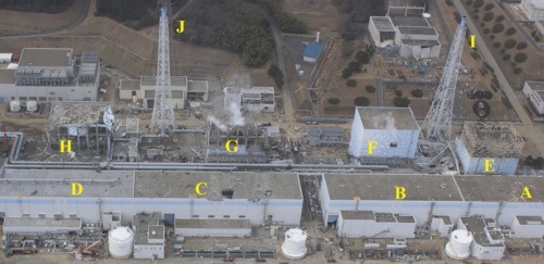
2A - Unit 1 turbine building containing the main turbine, main generator, condenser, condensate pumps, and condensate booster pumps
2B - Unit 2 turbine building containing the main turbine, main generator, condenser, condensate pumps, and condensate booster pumps
2C - Unit 3 turbine building containing the main turbine, main generator, condenser, condensate pumps, and condensate booster pumps
2D - Unit 4 turbine building containing the main turbine, main generator, condenser, condensate pumps, and condensate booster pumps
2E - Unit 1 reactor building with extensive damage caused by hydrogen explosion
2F - Unit 2 reactor building showing blow-out panel opened to relief hydrogen and vapor buildups
2G - Unit 3 reactor building with extensive damage caused by hydrogen explosion
2H - Unit 4 reactor building with extensive damage caused by hydrogen explosion
2I - Stack shared by the Unit 1 and Unit 2 reactor building exhaust system. Air from the reactor buildings is discharged from this stack during normal operations. During accident conditions, a system within the reactor building routes air through a charcoal filter system before sending it to the stack for discharge. The primary containment is vented through the reactor building charcoal filter system before flowing through the lines to the stack.
2J - Stack shared by the Unit 3 and Unit 4 reactor building exhaust system. Air from the reactor buildings is discharged from this stack during normal operations. During accident conditions, a system within the reactor building routes air through a charcoal filter system before sending it to the stack for discharge. The primary containment is vented through the reactor building charcoal filter system before flowing through the lines to the stack.
____________________________________________________________________
Photo 3: (original photo: Air Photo Service Co. Ltd., Japan)
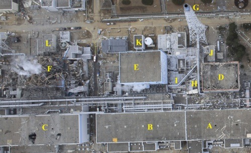
3A - Unit 1 turbine building containing the main turbine, main generator, condenser, condensate pumps, and condensate booster pumps
3B - Unit 2 turbine building containing the main turbine, main generator, condenser, condensate pumps, and condensate booster pumps
3C - Unit 3 turbine building containing the main turbine, main generator, condenser, condensate pumps, and condensate booster pumps
3D - Unit 1 reactor building with extensive damage caused by hydrogen explosion
3E - Unit 2 reactor building
3F - Unit 3 reactor building with extensive damage caused by hydrogen explosion
3G - Stack shared by the Unit 1 and Unit 2 reactor building exhaust system. Air from the reactor buildings is discharged from this stack during normal operations. During accident conditions, a system within the reactor building routes air through a charcoal filter system before sending it to the stack for discharge. The primary containment is vented through the reactor building charcoal filter system before flowing through the lines to the stack.
3H - Unit 1 reactor building (D) exhaust line to the stack (G)
3I - Unit 2 reactor building (E) exhaust line to the stack (G)
3J - Unit 1 truck bay used to deliver canisters of new fuel assemblies into the reactor building (D) and its refueling floor
3K - Unit 2 truck bay used to deliver canisters of new fuel assemblies into the reactor building (D) and its refueling floor
3L - Unit 3 truck bay used to deliver canisters of new fuel assemblies into the reactor building (D) and its refueling floor
_____________________________________________________________________
Photo 4: (original photo: Air Photo Service Co. Ltd., Japan)

4A - Unit 2 turbine building containing the main turbine, main generator, condenser, condensate pumps, and condensate booster pumps
4B - Unit 3 turbine building containing the main turbine, main generator, condenser, condensate pumps, and condensate booster pumps
4C - Unit 4 turbine building containing the main turbine, main generator, condenser, condensate pumps, and condensate booster pumps
4D - Unit 3 reactor building with extensive damage caused by hydrogen explosion
4E - Unit 4 reactor building with extensive damage caused by hydrogen explosion
4F - Unit 3 reactor building (D) exhaust line to the stack (H) showing extensive damage
4G - Unit 4 reactor building (E) exhaust line to the stack (H)
4H - Stack shared by the Unit 3 and Unit 4 reactor building exhaust system. Air from the reactor buildings is discharged from this stack during normal operations. During accident conditions, a system within the reactor building routes air through a charcoal filter system before sending it to the stack for discharge. The primary containment is vented through the reactor building charcoal filter system before flowing through the lines to the stack.
4I - Offgas building shared by all four units containing equipment to process air pulled from the condensers and reduce radioactivity discharged from the offgas stack during normal reactor operation
4J - Offgas stack discharging treated flow from Units 1-4 during normal operation
-------------------------------------------------------------
Репортаж 2:
Annotated Photos of Fukushima (continued)
Below are some additional annotated versions of high-resolution photographs of the Fukushima Dai-Ichi nuclear plant that have been posted on the web by cryptome.org. For annotated photos 1-4, click here.
Photo 5: (original photo: Air Photo Service Co. Ltd., Japan)
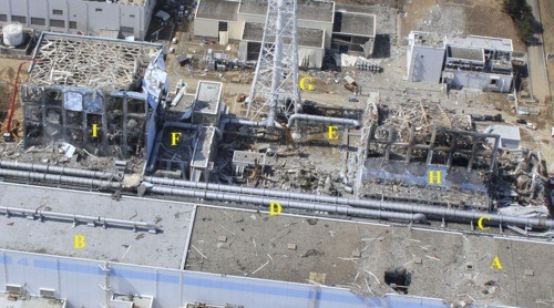
5A - Unit 3 turbine building containing the main turbine, main generator, condenser, condensate pumps, and condensate booster pumps
5B - Unit 4 turbine building containing the main turbine, main generator, condenser, condensate pumps, and condensate booster pumps
5C - Unit 2 offgas line that transports air pulled from the condenser inside the Unit 2 turbine building during normal operation to the offgas building for treatment to reduce radioactivity levels before discharge to the atmosphere
5D - Unit 3 offgas line that transports air pulled from the condenser inside the Unit 2 turbine building during normal operation to the offgas building for treatment to reduce radioactivity levels before discharge to the atmosphere
5E - Unit 3 reactor building (H) exhaust line to the stack (G) showing extensive damage
5F - Unit 4 reactor building (I) exhaust line to the stack (G)
5G - Stack shared by the Unit 3 and Unit 4 reactor building exhaust system. Air from the reactor buildings is discharged from this stack during normal operations. During accident conditions, a system within the reactor building routes air through a charcoal filter system before sending it to the stack for discharge. The primary containment is vented through the reactor building charcoal filter system before flowing through the lines to the stack.
5H - Unit 3 reactor building with extensive damage caused by hydrogen explosion
5I - Unit 4 reactor building with extensive damage caused by hydrogen explosion
_____________________________________________________________________
Photo 6: (original photo: Air Photo Service Co. Ltd., Japan)
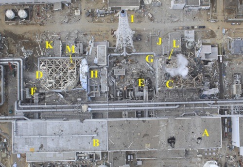
6A - Unit 3 turbine building containing the main turbine, main generator, condenser, condensate pumps, and condensate booster pumps
6B - Unit 4 turbine building containing the main turbine, main generator, condenser, condensate pumps, and condensate booster pumps
6C - Unit 3 reactor building with extensive damage caused by hydrogen explosion
6D - Unit 4 reactor building with extensive damage caused by hydrogen explosion
6E - Unit 3 main transformer showing three parallel bus ducts connecting the main transformer to the Unit 3 turbine building (A) housing the main generator
6F - Unit 4 main transformer showing three parallel bus ducts connecting the main transformer to the Unit 3 turbine building (B) housing the main generator
6G - Unit 3 reactor building (C) exhaust line to the stack (I) showing extensive damage
6H - Unit 4 reactor building (D) exhaust line to the stack (I)
6I - Stack shared by the Unit 3 and Unit 4 reactor building exhaust system. Air from the reactor buildings is discharged from this stack during normal operations. During accident conditions, a system within the reactor building routes air through a charcoal filter system before sending it to the stack for discharge. The primary containment is vented through the reactor building charcoal filter system before flowing through the lines to the stack.
6J - Unit 3 truck bay used to deliver canisters of new fuel assemblies into the reactor building (D) and its refueling floor
6K - Unit 4 truck bay used to deliver canisters of new fuel assemblies into the reactor building (D) and its refueling floor
6L - Unit 3 access hatch connecting the truck bay elevation with the refueling floor elevation inside the Unit 3 reactor building (C)
6M - Unit 4 drywell head (yellow). Unit 4 was in a refueling shutdown at the time with the drywell head and reactor vessel head removed to allow access to the reactor core.
_____________________________________________________________________
Photo 7: (original photo: Air Photo Service Co. Ltd., Japan)
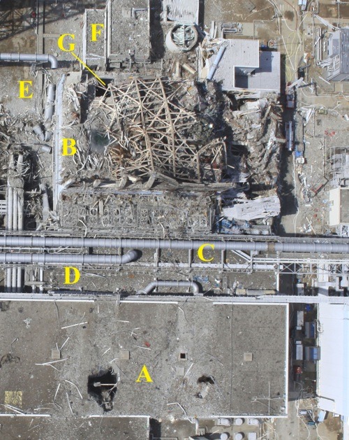
7A - Unit 3 turbine building containing the main turbine, main generator, condenser, condensate pumps, and condensate booster pumps. Roof damage possibly caused by debris from the Unit 3 reactor building (B) explosion
7B - Unit 3 reactor building with extensive damage caused by hydrogen explosion
7C - Unit 2 offgas line that transports air pulled from the condenser inside the Unit 2 turbine building during normal operation to the offgas building for treatment to reduce radioactivity levels before discharge to the atmosphere
7D - Unit 3 offgas line that transports air pulled from the condenser inside the Unit 2 turbine building during normal operation to the offgas building for treatment to reduce radioactivity levels before discharge to the atmosphere
7E - Unit 3 reactor building (B) exhaust line to the stack showing extensive damage
7F - Unit 3 truck bay used to deliver canisters of new fuel assemblies into the reactor building (B) and its refueling floor
7G - Unit 3 access hatch connecting the truck bay elevation with the refueling floor elevation inside the Unit 3 reactor building (B)
Фразы повторяются, меняются только номера блоков. но в целом примерно так
1 A,B,C,D (соотв.блок 1,2,3,4) - здание турбины, в котором - главная турбина, главный генератор, главный конденсатор, конденсатные насосы, бустерные насосы
1E здание, в котором газовые сдувки из конденсаторов всех четырех блоков очищаются от радиоактивности для снижения радиоактивных выбросов через венттрубу при нормальной эксплуатации
1F - Здание реактора блока 1, существенно поврежденное при взрыве водорода
1G - Здание реактора блока 2
1H - Здание реактора блока 3, существенно поврежденное при взрыве водорода
1I - Здание реактора блока 4, существенно поврежденное при взрыве водорода
1J - Венттруба для сброса газовых сдувок блоков 1-4 при нормальной эксплуатации
1K - Забор морской воды блока 1, откуда морская вода качается по подземным трубопроводам в конденсатор блока 1 (A)для охлаждения пара главной турбины. Подогретая морская вода сбрасывается по подземным трубопроводам в общий бетонный водовод до места сброса(N).
1L - Забор морской воды блока 2, откуда морская вода качается по подземным трубопроводам в конденсатор блока 1(B) для охлаждения пара главной турбины. Подогретая морская вода сбрасывается по подземным трубопроводам в общий бетонный водовод до места сброса(N).
1M - Забор морской воды блока 3 , откуда морская вода качается по подземным трубопроводам в конденсатор блока 1(C) для охлаждения пара главной турбины. Подогретая морская вода сбрасывается по подземным трубопроводам в общий бетонный водовод (N).
1N -Место сброса, общее для блоков 1,2,3,4 , где нагретая морская вода возвращается в Тихий океан
1O - Вентиляционная труба зданий реакторов 1 и 2 блоков. Воздух из зданий реакторов сбрасывается через эту трубу при нормальной эксплуатации. В аварийной ситуации воздух очищается на фильтрах с активированным углем до сброса через венттрубу. Контаймент вентилируется через венттрубу с предварительной очисткой на угольных фильтрах.
1P - Вентиляционная труба зданий реакторов 3 и 4 блоков. Воздух из зданий реакторов сбрасывается через эту трубу при нормальной эксплуатации. В аварийной ситуации воздух очищается на фильтрах с активированным углем до сброса в венттрубу. Контаймент вентилируется через венттрубу с предварительной очисткой на угольных фильтрах.
2F - Здание реактора блока 2 с панелью, выбитой для сброса водорода и пара
3H - Сбросной воздуховод здания реактора блока 1 (D) в венттрубу (G)
3I - Сбросной воздуховод здания реактора блока 2 (E) в венттрубу (G)
3J - Транспортный шлюз блока 1, предназначенный для доставки контейнеров со свежим топливом в здание реактора блока 1 (D)
6E - Главный трансформатор блока 3 с тремя параллельными токопроводами, соединяющими главный трансформатор с главным генератором, расположенным в здании турбины блока 3 (А)
6F - Главный трансформатор блока 4 с тремя параллельными токопроводами, соединяющими главный трансформатор с главным генератором, расположенным в здании турбины блока 3 (В)
6M - Блок 4 крышка колодца перегрузки (желтая). Блок 4 находился в состоянии останова для перегрузки топлива и крышка колодца и крышка ректора были сняты для доступа к активной зоне.
С форума "глобальной авантюры": http://www.avanturist.org/forum/index.php/topic,97.2900.html
Дэвид Локбаум, веселые и не очень истории которого из американских реакторных будней я приводил не раз, выложил два интересных репортажа пофукусимским снимкам высокого разреше. Переводить, увы, времени у меня нет. Если кто возьмется, низкий поклон:
Я тоже не буду, тут все просто, если что, есть гугл-переводчик
upd Внизу появился перевод (сорри, у меня времени нет, поэтому я его просто копирую с той же Авантюры.
Репортаж 1:
A set of very high-resolution photographs of the Fukushima Dai-Ichi nuclear plant have been posted on the web by cryptome.org. I’ve annotated some of those pictures below to help people know what they are seeing in those photos.
Photo 1: (original photo: Air Photo Service Co. Ltd., Japan)

1A - Unit 1 turbine building containing the main turbine, main generator, condenser, condensate pumps, and condensate booster pumps
1B - Unit 2 turbine building containing the main turbine, main generator, condenser, condensate pumps, and condensate booster pumps
1C - Unit 3 turbine building containing the main turbine, main generator, condenser, condensate pumps, and condensate booster pumps
1D - Unit 4 turbine building containing the main turbine, main generator, condenser, condensate pumps, and condensate booster pumps
1E - Offgas building shared by all four units containing equipment to process air pulled from the condensers and reduce radioactivity discharged from the offgas stack during normal reactor operation
1F - Unit 1 reactor building with extensive damage caused by hydrogen explosion
1G - Unit 2 reactor building
1H - Unit 3 reactor building with extensive damage caused by hydrogen explosion
1I - Unit 4 reactor building with extensive damage caused by hydrogen explosion
1J - Offgas stack discharging treated flow from Units 1-4 during normal operation
1K - Unit 1 intake where sea water is pumped via underground pipes into the condenser within the Unit 1 turbine building (A) to cool the steam exiting the main turbine. The warmed sea water flows through underground pipe to a common concrete culvert to the discharge point (N).
1L - Unit 2 intake where sea water is pumped via underground pipes into the condenser within the Unit 1 turbine building (B) to cool the steam exiting the main turbine. The warmed sea water flows through underground pipe to a common concrete culvert to the discharge point (N).
1M - Unit 3 intake where sea water is pumped via underground pipes into the condenser within the Unit 1 turbine building (C) to cool the steam exiting the main turbine. The warmed sea water flows through underground pipe to a common concrete culvert to the discharge point (N).
1N - Common discharge point used by Units 1, 2, 3, and 4 to return warmed sea water to the Pacific Ocean
1O - Stack shared by the Unit 1 and Unit 2 reactor building exhaust system. Air from the reactor buildings is discharged from this stack during normal operations. During accident conditions, a system within the reactor building routes air through a charcoal filter system before sending it to the stack for discharge. The primary containment is vented through the reactor building charcoal filter system before flowing through the lines to the stack.
1P - Stack shared by the Unit 3 and Unit 4 reactor building exhaust system. Air from the reactor buildings is discharged from this stack during normal operations. During accident conditions, a system within the reactor building routes air through a charcoal filter system before sending it to the stack for discharge. The primary containment is vented through the reactor building charcoal filter system before flowing through the lines to the stack.
____________________________________________________________________
Photo 2: (original photo: Air Photo Service Co. Ltd., Japan)

2A - Unit 1 turbine building containing the main turbine, main generator, condenser, condensate pumps, and condensate booster pumps
2B - Unit 2 turbine building containing the main turbine, main generator, condenser, condensate pumps, and condensate booster pumps
2C - Unit 3 turbine building containing the main turbine, main generator, condenser, condensate pumps, and condensate booster pumps
2D - Unit 4 turbine building containing the main turbine, main generator, condenser, condensate pumps, and condensate booster pumps
2E - Unit 1 reactor building with extensive damage caused by hydrogen explosion
2F - Unit 2 reactor building showing blow-out panel opened to relief hydrogen and vapor buildups
2G - Unit 3 reactor building with extensive damage caused by hydrogen explosion
2H - Unit 4 reactor building with extensive damage caused by hydrogen explosion
2I - Stack shared by the Unit 1 and Unit 2 reactor building exhaust system. Air from the reactor buildings is discharged from this stack during normal operations. During accident conditions, a system within the reactor building routes air through a charcoal filter system before sending it to the stack for discharge. The primary containment is vented through the reactor building charcoal filter system before flowing through the lines to the stack.
2J - Stack shared by the Unit 3 and Unit 4 reactor building exhaust system. Air from the reactor buildings is discharged from this stack during normal operations. During accident conditions, a system within the reactor building routes air through a charcoal filter system before sending it to the stack for discharge. The primary containment is vented through the reactor building charcoal filter system before flowing through the lines to the stack.
____________________________________________________________________
Photo 3: (original photo: Air Photo Service Co. Ltd., Japan)

3A - Unit 1 turbine building containing the main turbine, main generator, condenser, condensate pumps, and condensate booster pumps
3B - Unit 2 turbine building containing the main turbine, main generator, condenser, condensate pumps, and condensate booster pumps
3C - Unit 3 turbine building containing the main turbine, main generator, condenser, condensate pumps, and condensate booster pumps
3D - Unit 1 reactor building with extensive damage caused by hydrogen explosion
3E - Unit 2 reactor building
3F - Unit 3 reactor building with extensive damage caused by hydrogen explosion
3G - Stack shared by the Unit 1 and Unit 2 reactor building exhaust system. Air from the reactor buildings is discharged from this stack during normal operations. During accident conditions, a system within the reactor building routes air through a charcoal filter system before sending it to the stack for discharge. The primary containment is vented through the reactor building charcoal filter system before flowing through the lines to the stack.
3H - Unit 1 reactor building (D) exhaust line to the stack (G)
3I - Unit 2 reactor building (E) exhaust line to the stack (G)
3J - Unit 1 truck bay used to deliver canisters of new fuel assemblies into the reactor building (D) and its refueling floor
3K - Unit 2 truck bay used to deliver canisters of new fuel assemblies into the reactor building (D) and its refueling floor
3L - Unit 3 truck bay used to deliver canisters of new fuel assemblies into the reactor building (D) and its refueling floor
_____________________________________________________________________
Photo 4: (original photo: Air Photo Service Co. Ltd., Japan)

4A - Unit 2 turbine building containing the main turbine, main generator, condenser, condensate pumps, and condensate booster pumps
4B - Unit 3 turbine building containing the main turbine, main generator, condenser, condensate pumps, and condensate booster pumps
4C - Unit 4 turbine building containing the main turbine, main generator, condenser, condensate pumps, and condensate booster pumps
4D - Unit 3 reactor building with extensive damage caused by hydrogen explosion
4E - Unit 4 reactor building with extensive damage caused by hydrogen explosion
4F - Unit 3 reactor building (D) exhaust line to the stack (H) showing extensive damage
4G - Unit 4 reactor building (E) exhaust line to the stack (H)
4H - Stack shared by the Unit 3 and Unit 4 reactor building exhaust system. Air from the reactor buildings is discharged from this stack during normal operations. During accident conditions, a system within the reactor building routes air through a charcoal filter system before sending it to the stack for discharge. The primary containment is vented through the reactor building charcoal filter system before flowing through the lines to the stack.
4I - Offgas building shared by all four units containing equipment to process air pulled from the condensers and reduce radioactivity discharged from the offgas stack during normal reactor operation
4J - Offgas stack discharging treated flow from Units 1-4 during normal operation
-------------------------------------------------------------
Репортаж 2:
Annotated Photos of Fukushima (continued)
Below are some additional annotated versions of high-resolution photographs of the Fukushima Dai-Ichi nuclear plant that have been posted on the web by cryptome.org. For annotated photos 1-4, click here.
Photo 5: (original photo: Air Photo Service Co. Ltd., Japan)

5A - Unit 3 turbine building containing the main turbine, main generator, condenser, condensate pumps, and condensate booster pumps
5B - Unit 4 turbine building containing the main turbine, main generator, condenser, condensate pumps, and condensate booster pumps
5C - Unit 2 offgas line that transports air pulled from the condenser inside the Unit 2 turbine building during normal operation to the offgas building for treatment to reduce radioactivity levels before discharge to the atmosphere
5D - Unit 3 offgas line that transports air pulled from the condenser inside the Unit 2 turbine building during normal operation to the offgas building for treatment to reduce radioactivity levels before discharge to the atmosphere
5E - Unit 3 reactor building (H) exhaust line to the stack (G) showing extensive damage
5F - Unit 4 reactor building (I) exhaust line to the stack (G)
5G - Stack shared by the Unit 3 and Unit 4 reactor building exhaust system. Air from the reactor buildings is discharged from this stack during normal operations. During accident conditions, a system within the reactor building routes air through a charcoal filter system before sending it to the stack for discharge. The primary containment is vented through the reactor building charcoal filter system before flowing through the lines to the stack.
5H - Unit 3 reactor building with extensive damage caused by hydrogen explosion
5I - Unit 4 reactor building with extensive damage caused by hydrogen explosion
_____________________________________________________________________
Photo 6: (original photo: Air Photo Service Co. Ltd., Japan)

6A - Unit 3 turbine building containing the main turbine, main generator, condenser, condensate pumps, and condensate booster pumps
6B - Unit 4 turbine building containing the main turbine, main generator, condenser, condensate pumps, and condensate booster pumps
6C - Unit 3 reactor building with extensive damage caused by hydrogen explosion
6D - Unit 4 reactor building with extensive damage caused by hydrogen explosion
6E - Unit 3 main transformer showing three parallel bus ducts connecting the main transformer to the Unit 3 turbine building (A) housing the main generator
6F - Unit 4 main transformer showing three parallel bus ducts connecting the main transformer to the Unit 3 turbine building (B) housing the main generator
6G - Unit 3 reactor building (C) exhaust line to the stack (I) showing extensive damage
6H - Unit 4 reactor building (D) exhaust line to the stack (I)
6I - Stack shared by the Unit 3 and Unit 4 reactor building exhaust system. Air from the reactor buildings is discharged from this stack during normal operations. During accident conditions, a system within the reactor building routes air through a charcoal filter system before sending it to the stack for discharge. The primary containment is vented through the reactor building charcoal filter system before flowing through the lines to the stack.
6J - Unit 3 truck bay used to deliver canisters of new fuel assemblies into the reactor building (D) and its refueling floor
6K - Unit 4 truck bay used to deliver canisters of new fuel assemblies into the reactor building (D) and its refueling floor
6L - Unit 3 access hatch connecting the truck bay elevation with the refueling floor elevation inside the Unit 3 reactor building (C)
6M - Unit 4 drywell head (yellow). Unit 4 was in a refueling shutdown at the time with the drywell head and reactor vessel head removed to allow access to the reactor core.
_____________________________________________________________________
Photo 7: (original photo: Air Photo Service Co. Ltd., Japan)

7A - Unit 3 turbine building containing the main turbine, main generator, condenser, condensate pumps, and condensate booster pumps. Roof damage possibly caused by debris from the Unit 3 reactor building (B) explosion
7B - Unit 3 reactor building with extensive damage caused by hydrogen explosion
7C - Unit 2 offgas line that transports air pulled from the condenser inside the Unit 2 turbine building during normal operation to the offgas building for treatment to reduce radioactivity levels before discharge to the atmosphere
7D - Unit 3 offgas line that transports air pulled from the condenser inside the Unit 2 turbine building during normal operation to the offgas building for treatment to reduce radioactivity levels before discharge to the atmosphere
7E - Unit 3 reactor building (B) exhaust line to the stack showing extensive damage
7F - Unit 3 truck bay used to deliver canisters of new fuel assemblies into the reactor building (B) and its refueling floor
7G - Unit 3 access hatch connecting the truck bay elevation with the refueling floor elevation inside the Unit 3 reactor building (B)
Фразы повторяются, меняются только номера блоков. но в целом примерно так
1 A,B,C,D (соотв.блок 1,2,3,4) - здание турбины, в котором - главная турбина, главный генератор, главный конденсатор, конденсатные насосы, бустерные насосы
1E здание, в котором газовые сдувки из конденсаторов всех четырех блоков очищаются от радиоактивности для снижения радиоактивных выбросов через венттрубу при нормальной эксплуатации
1F - Здание реактора блока 1, существенно поврежденное при взрыве водорода
1G - Здание реактора блока 2
1H - Здание реактора блока 3, существенно поврежденное при взрыве водорода
1I - Здание реактора блока 4, существенно поврежденное при взрыве водорода
1J - Венттруба для сброса газовых сдувок блоков 1-4 при нормальной эксплуатации
1K - Забор морской воды блока 1, откуда морская вода качается по подземным трубопроводам в конденсатор блока 1 (A)для охлаждения пара главной турбины. Подогретая морская вода сбрасывается по подземным трубопроводам в общий бетонный водовод до места сброса(N).
1L - Забор морской воды блока 2, откуда морская вода качается по подземным трубопроводам в конденсатор блока 1(B) для охлаждения пара главной турбины. Подогретая морская вода сбрасывается по подземным трубопроводам в общий бетонный водовод до места сброса(N).
1M - Забор морской воды блока 3 , откуда морская вода качается по подземным трубопроводам в конденсатор блока 1(C) для охлаждения пара главной турбины. Подогретая морская вода сбрасывается по подземным трубопроводам в общий бетонный водовод (N).
1N -Место сброса, общее для блоков 1,2,3,4 , где нагретая морская вода возвращается в Тихий океан
1O - Вентиляционная труба зданий реакторов 1 и 2 блоков. Воздух из зданий реакторов сбрасывается через эту трубу при нормальной эксплуатации. В аварийной ситуации воздух очищается на фильтрах с активированным углем до сброса через венттрубу. Контаймент вентилируется через венттрубу с предварительной очисткой на угольных фильтрах.
1P - Вентиляционная труба зданий реакторов 3 и 4 блоков. Воздух из зданий реакторов сбрасывается через эту трубу при нормальной эксплуатации. В аварийной ситуации воздух очищается на фильтрах с активированным углем до сброса в венттрубу. Контаймент вентилируется через венттрубу с предварительной очисткой на угольных фильтрах.
2F - Здание реактора блока 2 с панелью, выбитой для сброса водорода и пара
3H - Сбросной воздуховод здания реактора блока 1 (D) в венттрубу (G)
3I - Сбросной воздуховод здания реактора блока 2 (E) в венттрубу (G)
3J - Транспортный шлюз блока 1, предназначенный для доставки контейнеров со свежим топливом в здание реактора блока 1 (D)
6E - Главный трансформатор блока 3 с тремя параллельными токопроводами, соединяющими главный трансформатор с главным генератором, расположенным в здании турбины блока 3 (А)
6F - Главный трансформатор блока 4 с тремя параллельными токопроводами, соединяющими главный трансформатор с главным генератором, расположенным в здании турбины блока 3 (В)
6M - Блок 4 крышка колодца перегрузки (желтая). Блок 4 находился в состоянии останова для перегрузки топлива и крышка колодца и крышка ректора были сняты для доступа к активной зоне.
С форума "глобальной авантюры": http://www.avanturist.org/forum/index.php/topic,97.2900.html