alexeiboiko
in
ru_4g
Литература по LTE. The Long Term Evolution IN BULLETS. PDCCH
Я уже как-то представлял эту книгу, адресованную всем, кто интересуется LTE. Ее автор Chris Johnson, старший инженер Nokia Siemens Networks.

Содержание >>>>
Где купить >>>>
Списавшись с г-ном Chris Johnson, я попросил его поделиться парой фрагментов его книги с нашим сообществом. Автор любезно пошел мне навстречу и предоставил соответствующее разрешение. Фрагменты, с одной стороны, являются тизерами, которые, возможно, кого-то побудят к покупке его книги, с другой стороны, представляют из себя полезную информацию по интересующей нас теме.
Сегодня Chris прислал фрагменты и я рад их вам предложить.
6.4 PDCCH


(с) Материал предоставлен автором эксклюзивно для сообщества ru_4G и сайта MForum.ru.

Содержание >>>>
Где купить >>>>
Списавшись с г-ном Chris Johnson, я попросил его поделиться парой фрагментов его книги с нашим сообществом. Автор любезно пошел мне навстречу и предоставил соответствующее разрешение. Фрагменты, с одной стороны, являются тизерами, которые, возможно, кого-то побудят к покупке его книги, с другой стороны, представляют из себя полезную информацию по интересующей нас теме.
Сегодня Chris прислал фрагменты и я рад их вам предложить.
6.4 PDCCH
- The Physical Downlink Control Channel (PDCCH) is used to transfer Downlink Control Information (DCI). The detailed content of DCI is described in section 9
- The PCFICH signals the number of OFDMA symbols which can be occupied by the PDCCH. These symbols are always at the start of each subframe
- Resource elements allocated to the PDCCH are grouped into quadruplets (groups of 4 resource elements). The number of quadruplets available to the PDCCH is equal to the number of quadruplets within the set of OFDMA symbols signalled by the PCFICH, which have not already been allocated to the PCFICH, PHICH or Reference Signals
- Resource element quadruplets are grouped into Control Channel Elements (CCE). There are 9 quadruplets within a single
- CCE, i.e. 36 resource elements per CCE. The PDCCH uses QPSK modulation so a single CCE can transfer 72 bits
- 3GPP TS 36.211 specifies 4 PDCCH formats. These are presented in Table 30

- The PDCCH format is selected according to the size of the DCI. DCI bits have a 16 bit CRC attached prior to rate 1/3 channel coding and rate matching. The PDCCH format must offer sufficient capacity to avoid puncturing the DCI bits too heavily during rate matching
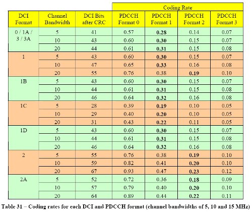
- Table 31 presents the coding rate for each DCI and PDCCH format. The coding rate is calculated as the ratio of the number of DCI bits after CRC attachment to the capacity of the PDCCH. The entries in bold represent the lowest PDCCH format which avoids the requirement for puncturing (coding rates greater than 0.33 require puncturing)

- Larger coding rates require more puncturing and have less redundancy to protect the DCI bits from the propagation channel. Larger coding rates could be used when coverage conditions are good.
- The number of CCE available depends upon the channel bandwidth and the number of OFDMA symbols allocated to the PDCCH. It also depends upon the number of Resource Element quadruplets used by the PHICH and whether or not 4х4 MIMO is used. Table 32 presents the maximum number of available CCE assuming no quadruplets have been allocated to the PHICH and 4х4 MIMO is not used.

- The maximum number of CCE is relatively small when only a single OFDMA symbol is allocated to the PDCCH
- A subset of the CCE shown in Table 32 will be required to broadcast DCI for system information and paging purposes. A further subset can be used to broadcast DCI for power control purposes. This reduces the total number of CCE available for allocating user plane resources
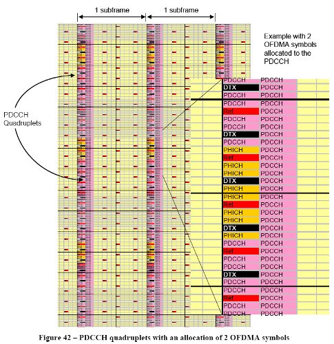
- Figure 42 illustrates the Resource Elements available to the PDCCH when 2 OFDMA symbols are allocated. The first OFDMA symbol is shared between the Reference Signal, PCFICH, PHICH and PDCCH, whereas the second OFDMA symbol is dedicated to the PDCCH

- The example shown in Figure 42 assumes a normal PHICH duration. An extended PHICH duration requires that at least 3 OFDMA symbols are allocated to the PDCCH. In that case, the PHICH would be distributed across the first 3 OFDMA symbols
- Individual UE are not required to decode all PDCCH DCI when searching for paging messages, system information, power control commands or user plane resource allocations. Common and UE specific ‘search spaces’ are defined to help restrict the quantity of decoding that each UE has to complete. These search spaces are described in section 9.2
- The PDCCH represents an overhead which reduces the number of resource elements available for user plane data
- the overhead increases as more OFDMA symbols are allocated to the PDCCH
- the overhead increases when the extended cyclic prefix is used
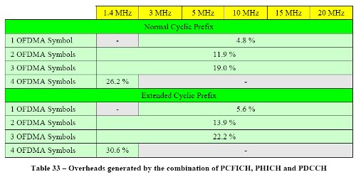
- Table 33 presents the combined overhead of the PCFICH, PHICH and PDCCH as a function of the number of symbols allocated to the PDCCH. These figures exclude the overhead generated by the Reference Signal (this should be added separately using the figures in Table 23). The overheads presented in Table 33 are applicable to either 1 or 2 transmit
- antenna ports. The figures in Table 33 decrease when 4х4 MIMO is used but the reference signal overheads increase

- 3GPP References: TS 36.211
(с) Материал предоставлен автором эксклюзивно для сообщества ru_4G и сайта MForum.ru.