Steampunk Geiger Counter, Conclusion

The Geiger counter is still a lashed-up mess of clip leads and greasy junk on my workbench, but as I mentioned in my last daywander, it does work, and detects the radium paint on a couple of sixty-year-old military aviation panel meters. I may not be able to work on it much for the next few weeks, so in this entry I'm going to summarize what I've learned so far.

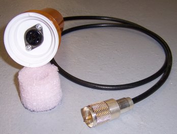
But first, a couple of notes on the probe I made. I noticed years ago that a species of pill bottle with a two-way cap allows two bottles to be connected at the cap. It occurred to me that one of these bottles was by sheer chance just about the size of an Amperex 75NB3 Geiger tube. So I mounted the JEDEC A3-1 socket in the cap, and cut a foam doughnut with an Exacto knife so that it would fit (with just a little compression) inside one of the bottles. A 5/8" hole in the doughnut keeps the Geiger tube centered and immobile inside the bottle. I put a PL-259 on the cable because I have a lot of PL-259's here, and they have a pleasing sort of retro look to them, especially after they tarnish. (This one was new from a sealed bag. It won't look so shiny next year.)
My first conclusion, after a huge amount of time spent trying things, is that it's not easy getting to 900V with nothing more than a pushbutton, a spark gap, and 3V worth of batteries. In fact, the best I could do was barely break 700V, which is right on the edge of what allows this particular tube to operate. (Smaller tubes like the CK-1026 may work at lower voltages.) Change out the spark gap for a 1N4007 silicon rectifier and you're at 900V in twenty pushes of the button--more with a larger cap, less with a smaller cap. The transformer matters crucially. The one I'm using has a 1:14 turns ratio, which is very uncommon.
My second conclusion is that the sort of greasy black bakelite barrier terminal strips that I used for the spark gap and general connections are very leaky at high voltage. The caps are mounted on a steatite bar, which is very low-loss, and when I soldered everything else together in a sort of self-supporting wad in mid-air, the charge stayed on the caps almost twice as long. Obvious in hindsight, but I never thought about it when I was putting the thing together. The final device will be assembled with this in mind. If it doesn't look especially retro, that's ok.
My third conclusion is that some sort of amplification is necessary. With 900V on the tube I could clearly hear the clicks indicating activity, but they were not loud and this was in a workshop as quiet as most tombs, at least those lacking zombies and poltergeists. I set up a small homebrew two-tube speaker audio amp on the bench (lineup: 6AV6-6AQ5A) and piped the tube's output into it. Suddenly the clicks filled the room, and I'm guessing that some of those may not have been heard with the tube running barefoot into headphones. A portable hip-hung retro counter would use battery tubes, of which I have many.
I'm still working on several elements of the design, particularly a better way to charge the caps than pushing a button twenty times. I'm almost ready to test a rotary interrupter that will be operated with a crank. I also have a small hand-cranked telephone magneto that generates 120VAC, and much can be done with that.
But as for whether a truly steampunk (i.e., no active devices) Geiger counter is possible, the answer is a qualified yes. A skilled and patient mad scientist from 1900 could do it. He might have to wind his own step-up transformer, but if I can get to 700V with greasy junk and a spark gap, 900V is not out of reach. I consider myself a citizen scientist but I'm not especially mad, and unlike most mad scientists I have a wife, dogs, and a driveway to shovel in colder weather. That being the case, I'm bringing this research project to a close. I will build a Geiger counter, but it's going to be more 1950 than 1900. I'll continue to discuss the project here under a different title. Deco Geiger Counter? Deiselpunk Geiger Counter? Still thinking about that, but you'll know it when you see it.